Diecast car racing is a fun hobby, but timing races with a stopwatch can be cumbersome. Building your own diecast racing timer adds a new dimension to the hobby. It allows for accurate timekeeping, creating a more competitive and engaging experience. This guide will walk you through the process of building your own diecast racing timer, from gathering the necessary components to programming and testing the final product. With a little effort and some basic electronics knowledge, you can create a professional-grade timer that enhances your racing experience.
What You’ll Need to Build a Diecast Racing Timer
Before you begin, gather all the necessary components and tools. This ensures a smooth and efficient building process. The components can be purchased online from electronics suppliers. Careful selection of components is crucial for the timer’s accuracy and reliability. Having the right tools at hand will also make assembly easier and more enjoyable, allowing for a cleaner and more professional-looking final product. It is a good idea to check component compatibility before purchasing to prevent issues later on.
Essential Components
The core of your diecast racing timer will consist of several key components that work together to measure and display race times. Each component plays a vital role in the timer’s overall functionality. The choice of components impacts the accuracy, display quality, and overall performance of your racing timer. Some components can be substituted based on budget and preferences, but the main function must always be considered.
Microcontroller Board
This is the brain of your timer, responsible for processing sensor inputs and controlling the display. An Arduino board is a popular choice due to its ease of use and readily available code examples. Other options include Raspberry Pi Pico or other similar development boards. Ensure the board has enough digital input/output pins to connect the sensors and the display. Select the board based on your programming knowledge and project requirements, as some boards offer more advanced features than others.
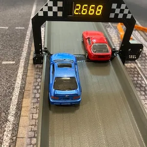
Sensors for Detecting Cars
Sensors are needed to detect when a diecast car crosses the finish line. Infrared (IR) sensors or photo-reflective sensors are common choices, as they are affordable and easy to implement. These sensors can detect the presence of a car based on the reflection or interruption of an IR beam. Consider the track width and car size when choosing the sensor’s detection range. Ensure the sensors are properly aligned and positioned to accurately register each car’s crossing of the finish line. Using multiple sensors across the finish line can improve accuracy.
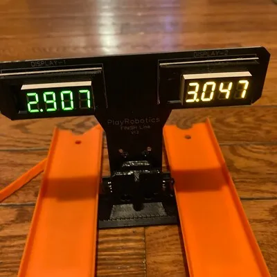
Display Unit
The display unit shows the race times. A seven-segment LED display or an LCD screen are common choices. Seven-segment displays are simpler but can only display numbers, while LCD screens can display more information, such as lap times, rankings, and even race names. Choose a display that is easy to read from a distance. Consider the number of digits and lines needed for the information you want to display. Ensure the display is compatible with the microcontroller’s output signals.
Power Supply
You’ll need a power supply to power all the electronic components. A 9V battery or a USB power adapter are typical choices. The power supply’s voltage and current capacity must match the components’ requirements. When selecting a power supply, make sure it can provide enough power to all the connected components simultaneously. Consider the mobility of your timer when choosing the power source. Using a rechargeable battery is also an eco-friendly option.
Tools Required
Besides components, you’ll need tools to assemble and connect them. Some tools are for assembly and others are for testing. Investing in good-quality tools makes the process much more convenient and yields better results. Having the right tools not only aids in the assembly but also ensures the longevity of your timer.
Soldering Iron and Solder
Soldering is often necessary to connect the components, especially when dealing with electronic circuits. A soldering iron and solder are essential. Learn basic soldering techniques to create reliable electrical connections. Make sure to use appropriate safety measures while soldering. A soldering iron stand helps to prevent accidents. When selecting solder, choose one that is appropriate for electronics and your soldering iron’s temperature range.
Wire Cutters and Strippers
These tools are crucial for preparing the wires used to connect the various components. Wire cutters and strippers allow you to cut wires to the correct length and strip the insulation without damaging the wire. Having the correct tools ensures neat and reliable connections. Wire strippers with adjustable settings are particularly useful for handling various wire gauges. Use wire cutters and strippers to cleanly prepare wires for connection.
Screwdrivers
Screwdrivers are needed for assembling the casing and securing the components. Have a set of small screwdrivers, including Phillips head and flathead, in different sizes. Ensure the screwdrivers match the screws used for the casing and component mounting. It is a good idea to have a magnetic screwdriver as it can help hold small screws. Always use the correct screwdriver size to avoid damaging the screw heads.
Building the Diecast Racing Timer
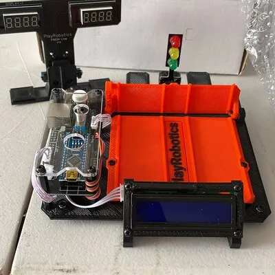
With all components and tools at hand, it’s time to build the timer. Follow these steps to ensure a functional and reliable timer. This phase involves the physical assembly and wiring of the components. Take your time, and double-check each connection to prevent errors. The physical build will determine how the timer looks and functions. A neat build also aids in troubleshooting in case of problems.
Assembling the Components
Start by assembling the components on a breadboard or a custom-designed PCB. A breadboard is useful for prototyping, while a PCB offers a more permanent and organized solution. Arrange the components according to your circuit diagram. Use jumper wires or solder to connect the components as per the circuit diagram. Double-check your connections before proceeding to the next step. Ensure that all the components are securely placed.
Wiring the Sensors
Connect the sensors to the microcontroller. Consult the sensor’s datasheet for the correct wiring configuration. Typically, you will connect the sensor’s power, ground, and signal pins to the microcontroller. If using IR sensors, position them carefully to detect the cars accurately as they cross the finish line. Test the sensor’s functionality by checking the output signal using a multimeter or an oscilloscope. Verify each sensor’s connection to eliminate errors.
Connecting the Display
Connect the display unit to the microcontroller. The wiring process will vary depending on the type of display you are using. For a seven-segment display, connect each segment to the microcontroller through current-limiting resistors. If using an LCD, refer to its datasheet for wiring instructions. Make sure to connect the display’s power and ground to the appropriate pins on the microcontroller. The correct connections ensure that the display works seamlessly with the microcontroller.
Powering Up and Testing

Connect the power supply to the circuit and turn it on. At this stage, no display and sensors will be active. You should see the display light up and the microcontroller initializing. Verify that all the components are receiving power. If you have not uploaded the code, you may see default values on the display. Once powered, use a multimeter to check for any short circuits or voltage irregularities. Do not proceed further if there are any issues.
Programming the Microcontroller
Programming is where you instruct the microcontroller on how to interpret sensor data and display the race times. You’ll need to write code that reads sensor inputs, calculates the time, and sends the information to the display. There are numerous resources available online to help you with programming the microcontroller. This requires knowledge of a programming language, like C++ for Arduino. Thorough programming makes the timer work the way you expect.
Downloading the Code
You’ll need a code editor, such as the Arduino IDE or Visual Studio Code, to write the code. In the editor, write the code to read the sensor inputs, calculate the elapsed time, and display the results. You can find plenty of code examples online. Carefully review and understand the code before uploading it to the microcontroller. Download the code using the code editor to your computer. Create a backup copy of your code.
Uploading the Code

Connect the microcontroller to your computer using a USB cable. Select the correct board and port in the code editor. Upload the code to the microcontroller. After the code is uploaded, the timer is ready for testing. Check that the display shows the correct information. Resolve any errors and re-upload the code. If you get errors, double-check the connections and ensure that the correct drivers are installed.
Customizing the Timer
After the initial upload, you can customize the timer. Modify the code to add features such as lap times, race rankings, or even a countdown timer. Add additional features to enhance user experience. The possibilities are endless, limited only by your creativity and the microcontroller’s capabilities. Always back up your original working code before making any customizations.
Fine-tuning the Timer
After building and programming, you may need to fine-tune the timer for optimal performance. Accurate timekeeping is crucial in racing, so you need to ensure the timer works correctly. This includes calibrating the sensors and adjusting the display settings.
Sensor Calibration
Calibrate the sensors to ensure accurate detection of cars crossing the finish line. Adjust the sensor sensitivity to avoid false triggers. Experiment with sensor positioning and angling to find the optimal setup for your track. This will help to avoid instances where the sensor does not register a car. If using IR sensors, ensure there is no ambient light interfering with the sensor’s beam. Proper calibration improves the accuracy of the timer.
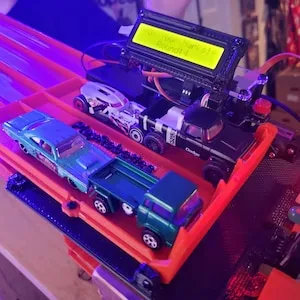
Display Adjustments
Adjust the display settings for optimal visibility. Adjust the brightness and contrast for easy viewing. Modify the display format to show the information you need. Ensure that the display is readable under various lighting conditions. A properly adjusted display enhances the user experience. Fine-tuning the display can improve the timer’s ease of use during races.
Troubleshooting Common Issues
Troubleshooting is a crucial part of any DIY project, and building a diecast racing timer is no exception. Problems may arise during the build, so knowing how to troubleshoot them is essential. Some of the common issues and solutions are described below. By following these steps, you can diagnose and fix common issues. Make sure to have a multimeter for testing and troubleshooting.
Sensor Not Detecting Cars
If the sensors are not detecting the cars, check the wiring connections and sensor alignment. Ensure the sensors are receiving power. Verify the sensor’s sensitivity settings, and adjust if necessary. Test the sensors by manually interrupting the beam. The problem could also be in the code; make sure that the program is designed to correctly read sensor inputs. If possible, try replacing the sensor to check if it is working. Check if there are any obstructions blocking the sensor’s beam.
Display Showing Incorrect Times
If the display shows incorrect times, double-check the code for any errors in the timing calculations. Recalibrate the sensors. Verify the clock frequency of the microcontroller, as it can affect the timekeeping accuracy. Check for any issues with the sensor’s signal. Check whether the display is connected correctly. If necessary, try to reset the microcontroller to its default settings. Ensure that the sensors are properly calibrated. Sometimes, even small errors can cause incorrect timing.
Timer Not Powering On
If the timer does not power on, check the power supply and wiring connections. Verify that the power supply’s voltage and current are appropriate. Use a multimeter to check for any short circuits or voltage drops. Check the power switch. If the microcontroller is not receiving power, the timer will not work. Ensure that the microcontroller is properly connected. Test with a different power source.
Building a diecast racing timer is a rewarding project that enhances the fun of diecast car racing. This guide provides a comprehensive overview. Follow these steps to construct your own timer. With a little effort, you can build a functional and accurate timer that takes your racing experience to the next level. Experiment with different features and customize the timer to fit your needs. Happy racing!